
These are my complete notes for Stream Ciphers in Symmetric Cryptography.
I color-coded my notes according to their meaning - for a complete reference for each type of note, see here (also available in the sidebar). All of the knowledge present in these notes has been filtered through my personal explanations for them, the result of my attempts to understand and study them from my classes and online courses. In the unlikely event there are any egregious errors, contact me at jdlacabe@berkeley.edu.
Summary of Stream Ciphers (Symmetric Cryptography)
Table Of Contents
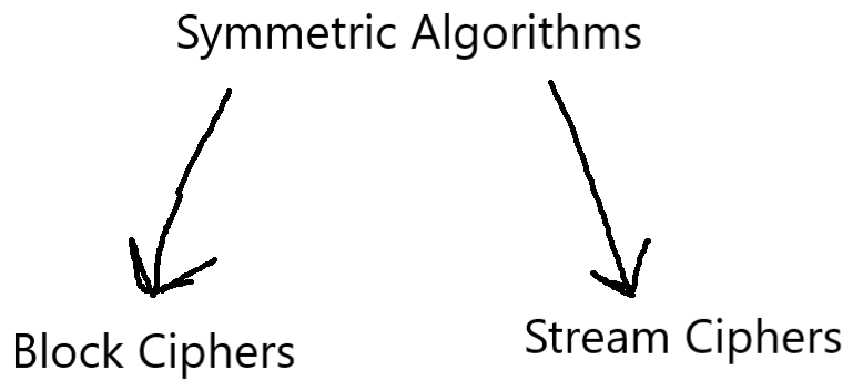
III. Stream Ciphers.
III.I Introduction to Stream Ciphers.
#
C. Rule .
Modular 2 Operations:
In cryptography, when considering all of the mathematical operations commonly applied in primitives and ciphers, the modular 2 operation carries with it a set of properties and a reputation that makes it unique even within modular arithmetic.
Mod 2 addition and subtraction are the same operation. Multiplication complicates things, but in all instances where the mod 2 function is limited to addition or subtraction, the results will be identical no matter which operation is applied.
With the smallest possible modulus that allows room for variation in the remainder, mod 2 operations are by and large the most popular application of modular arithmetic in cryptography. This is because their restriction of all numbers to be either 0s or 1s (by the very nature of a modular operation, see Rule 11) successfully emulates binary representation, making them extremely useful for bit-based computation (and in particular ciphers that intake streams of data, like stream ciphers (see Rule 25)).
The modular 2 operation is used so often, it has its own symbol in cryptographic diagrams: a circle with a cross. See Rule 25 for an example. In electrical engineering, the mod 2 function is known as the XOR gate, a type of binary gate (see E.E. [[[[[), further showcasing the broader importance of modular 2 operations in science as a whole.
Note that the listed properties do NOT extend to the modulus of any other number - only for two. See the Vigenère Cipher (see Rule 21), which works akin to a stream cipher, for proof using mod 26 (hint: the addition and subtraction operations produce different values).
#
C. Rule .
Stream Ciphers
Mathematical Definition:
(xi, yi, si) ∈ ℤ2
Encryption: esi(xi) ≡ (xi + si) mod 2
Decryption: dsi(yi) ≡ (yi + si) mod 2
xi = The Plaintext bit at index i.
yi = The Ciphertext bit at index i.
si = The "Keystream" at index i, equivalent to 'k' (as in past ciphers). Here, it is the Key (at index i) fed into the encryption and decryption functions.
ℤ2 = A ring of the first 2 integers: {0, 1}. See Subsection II.III for an explanation of rings.
esi(xi) = Encryption function, a mathematical formula that converts each x bit into a y bit.
dsi(yi) = Decryption function, a mathematical formula that converts each y bit into an x bit.
mod 2 = The modulus/remainder operator with respect to 2. Numbers can only be 0 or 1 in this reality - see Rule 24 for a full treatise.
Explanation:
A cipher that encrypts bits individually, processing one bit after another in a sequence. This is opposed to a Block Cipher (see Section IV), which takes in large numbers of bits all at once.
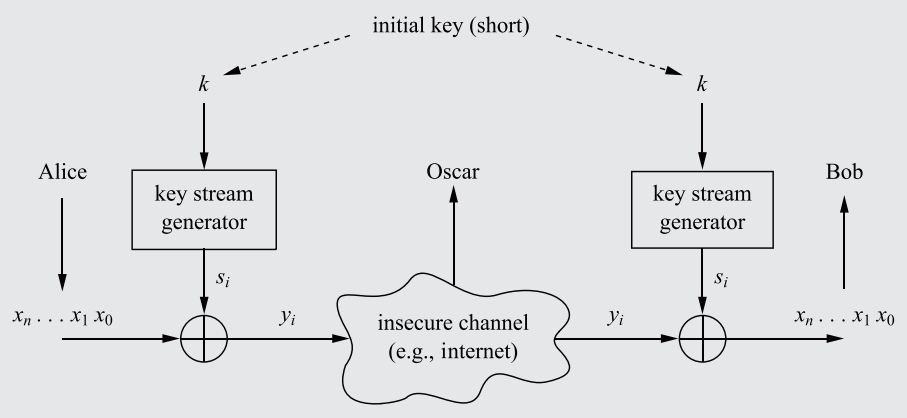
Using the modular 2 operation (see Rule 24), the encryption and decryption functions of the basic stream cipher can be depicted as shown in Fig. 4.
The central complexity of the Stream Cipher is the generation of the "Keystream", e.g. the stream of bits with which the plaintext is encrypted. This generation must be performed through Random Numbers - see Rule 26.
If the keybit (si) is zero, then the plaintext bit will pass through unchanged, but if the keybit is 1, then the plaintext bit will flip (like binary). Thus, if the keystream (by divine intervention) is straight 0's, then the plaintext will go unencrypted.
Mathematical Definition:
(xi, yi, si) ∈ ℤ2
Encryption: esi(xi) ≡ (xi + si) mod 2
Decryption: dsi(yi) ≡ (yi + si) mod 2
xi = The Plaintext bit at index i.
yi = The Ciphertext bit at index i.
si = The "Keystream" at index i, equivalent to 'k' (as in past ciphers). Here, it is the Key (at index i) fed into the encryption and decryption functions.
ℤ2 = A ring of the first 2 integers: {0, 1}. See Subsection II.III for an explanation of rings.
esi(xi) = Encryption function, a mathematical formula that converts each x bit into a y bit.
dsi(yi) = Decryption function, a mathematical formula that converts each y bit into an x bit.
mod 2 = The modulus/remainder operator with respect to 2. Numbers can only be 0 or 1 in this reality - see Rule 24 for a full treatise.
Explanation:
A cipher that encrypts bits individually, processing one bit after another in a sequence. This is opposed to a Block Cipher (see Section IV), which takes in large numbers of bits all at once.
Using the modular 2 operation (see Rule 24), the encryption and decryption functions of the basic stream cipher can be depicted as shown in Fig. 4.
The central complexity of the Stream Cipher is the generation of the "Keystream", e.g. the stream of bits with which the plaintext is encrypted. This generation must be performed through Random Numbers - see Rule 26.
If the keybit (si) is zero, then the plaintext bit will pass through unchanged, but if the keybit is 1, then the plaintext bit will flip (like binary). Thus, if the keystream (by divine intervention) is straight 0's, then the plaintext will go unencrypted.
# Fig. 4. - Practical Stream Ciphers:
# Keystream: A stream of characters that is combined with the plaintext to produce the ciphertext in a Stream Cipher, or, in the case of asynchronous stream ciphers, combined with a previous ciphertext to produce a new ciphertext.
The keystream is derived from the key and the seed. Generally, the keystream is denoted as "si", while the seed itself is s0, the initial position/keybit of the stream from which all recursive stream ciphers evolve from in their encryption functions. Inherently, the number of possible seeds is the same as the keyspace, since the number of seeds dictates how many keys there can be.
The creation of a keystream (both key and seed) involves random number generators, which are detailed in Subsection III.II. The seed, for example, may be created using an actual True Random Number Generator (see Rule 26), while the rest of the key will be deterministically generated from that seed using a PRNG (also Rule 26).
# Synchronous Stream Cipher: A Stream Cipher in which the keystream depends solely on the key, generated independently of the plaintext or ciphertext. Examples include Salsa20 & ChaCha.
# Asynchronous Stream Cipher: A Stream Cipher in which the keystream depends on the ciphertext in addition to the key - the key generation is reliant on previous ciphertext, making it a risky operation. An example is the Cipher Feedback (CFB) mode, described in Rule [[[.
III.II Random Number Generation.
#
C. Rule .
Random Number Generators (RNG):
The means with which a system can generate random numbers, for the purposes of constructing/filling a keystream with random bits, are split into three main mechanisms:
The means with which a system can generate random numbers, for the purposes of constructing/filling a keystream with random bits, are split into three main mechanisms:
- True Random Number Generators (TRNGs): "True" random numbers stem from random physical processes that cannot be reproduced. Such natural sources of entropy include flipping a coin, rolling a die, thermal noise, mouse movement, and keystroke timing.
Hardware and cryptographic systems have tried a lot of different techniques over the years to create a TRNG by analyzing/recording internal characteristics of the computer. Most modern CPU's have a TRNG within a TPM (trusted platform module) on the motherboard.
An example of a cipher that completely uses TRNGs (not just for one element like the seed, but for the entire keystream) is the One Time Pad, detailed in Rule 27. - Pseudo Random Number Generators (PRNGs): An RNG system that is random, but reproducable. Because PRNG's are computed, they are inherently deterministic processes. Since they are deterministic, Alice and Bob can generate the same keystream independently of one another, only needing to know the initial "seed", which is like the key for the key (see the "Keystream" definition).
With respect to Stream Ciphers, another commonly-used term is "PRBS" (Pseudo-Random Bit/Binary Sequences), which is just a more stream-specific way of looking at what these generators are actually producing.
Often, PRNG's are computed with the following function:
si+1 = f(si)
s0 = The initial seed value, which may be an actual TRNG.
f(si) = The 'randomizer' function, which performs whatever upon the seed in order to computationally randomize it.
This recursive generation is the form taken by the Linear Congruential Generator, an example of a cryptosystem utilizing a PRNG (see Rule 28).
The rand() function in C is a PRNG and uses a seed of 12345, with the following function as the randomizer:
Si+1 = ((1103515245 × si) + 12345) mod 2³¹. - Cryptographically Secure Pseudorandom Number Generators (CSPRNGs/CPRNGs): PRNG's that have an additional property: the numbers must be unpredictable.
Given n output keybits (si, si+1, ..., si+(n-1)), it is computationally infeasible to construct si+n.
While in most applications (read: the world outside cryptography), PRNG systems are perfectly fine and suited to create 'random' numbers for whatever purpose, they form very unsecure cryptosystems due to their inherently deterministic nature, and thus in Cryptography, the additional property of unpredictability is required. An example of a commonly-used CPRNG in the real world is the [[[.
# Unconditional Security: A cipher is "unconditionally secure" (or "information-theoretically secure") if it cannot be broken even with infinite computing resources.
Even if a key is 2^1000 bits, it would not be considered "unconditionally secure", because 2^1000 computers (a patently not infinite amount of computers) would be able to break the key in one second. This is despite the fact that such levels of computing power will never be realized in human history.
Thus, though there are very many ciphers that are "practically" secure (forming the backbone of our modern cybersecurity systems), they are not unconditionally secure.
# Computational Security: A cryptosystem is computationally secure if the best known algorithm for breaking it requires at least t operations, where 't' is some ridiculous number far beyond the reach of modern brute-force computational abilities.
#
C. Rule .
One Time Pad (OTP)
The One Time Pad (also referred to as the "Vernam cipher") is an example of a TRNG-based cryptosystem. It is the unconditionally secure, totally unbreakable, perfect encryption algorithm. The OTP is a stream cipher with the following properties:
1) The Keystream bits si must originate from a True Random Number Generator (a 'TRNG', see Rule 26, 1.).
2) Each Keystream bit must be used only once.
Knowledge of the Keystream must be exclusively limited to the involved parties, of course. At the end of the data transfer, the party that received the data must destroy the key so that it cannot be used by another party to decrypt the message after the fact. This is the same reason why reusing keys is extremely risky and nullifies the security benefits of the OTP.
The security of cryptosystem draws from the fact that, without knowledge of the keystream, even a brute-force attack would be futile, because any two text strings are equally as probable to be a particular word in the plaintext: if a four letter word were to be encrypted, it is equally probable for it to be "when", "stop", or "abcd".
There is one fundamental drawback of the OTP, however, that prevents its universal application: since keystream bits cannot be reused, the key has to be as long as the plaintext. A 400MB file, 8 bits to the byte, would entail a 3.2GB key. As such, the One Time Pad is not the be-all-end-all of Cryptography (at least in terms of application), and other types of CPRNGS are still relevant.
#
C. Rule .
Linear Congruential Generator (LCG):
Mathematical Definition:
(A, B, i, Si) ∈ ℤm
i > 0
Key K = (A, B)
Si + 1 ≡ ((A × Si) + B) mod m
S0 = The initial seed value, which may have been created using a TRNG. Of course, it is not depicted in the equation as the equation only refers to i > 0. The seed value is exactly ⌈log2 m⌉ bits long, explained below.
Si = The Keystream at index i, where i > 0. It is exactly ⌈log2 m⌉ bits long, explained below.
Si + 1 = The following value in the keystream, which is recursively calculated using the value of the previous bit in the keystream (along with the key). It is exactly ⌈log2 m⌉ bits long, explained below.
A = The multiplied value of the key. It is exactly ⌈log2 m⌉ bits long, explained below.
B = The "shift parameter" value of the key, only used for the addition operation. It is exactly ⌈log2 m⌉ bits long, explained below.
ℤm = A ring of m integers. See Subsection II.III for an explanation of rings.
mod m = The modulus/remainder operator, which represents the usage of modular arithmetic, with all numbers represented by their remainder with respect to m.
Explanation:
The LCG is a PRNG-based keystream generator, using the attributes of the key and the seed as its base components. It is an example of a non-cryptographically secure PRNG, the 2nd type of RNG detailed in Rule 26. This makes it more practical a system than the One Time Pad (see Rule 27), but much easier to break (see Rule 29). The keystream is deterministically created using a recursive function originating at S0 (the seed), which itself may be created using a TRNG.
Of course, separate from the nature of the function/equation itself, note that there are no "Encryption" or "Decryption" functions, because the given equation is merely for composing the keystream (PRNG-style - see Rule 26), while the equation for the Stream Cipher itself remains the same (see Rule 25).
The Linear Congruential Generator bears many similarities to the Affine Cipher (Rule 22), in particular how the key is split into multiple parameters (in the case of the LCG, the key used to generate the keystream). However, the length of the parameters greatly differs between the two - while affine ciphers have a set, immutable value for their keyspace, LCG variables derive their length from the modulus itself.
Note that because the modulus represents a set/ring, ℤm, m qualifies for the set-based bit-length (as detailed in Rule 4). As such, the fact that variables A, B, and Si are all ⌈log2 m⌉ bits long means that they are as long as the bit-length of the modulus.
Of course, since m is not the keyspace, ⌈log2 m⌉ is only in reference to a set-based bit-length and not to the key-length. As such, no determination regarding the keyspace of the LCG can be made from ⌈log2 m⌉, as the equation for finding it using a set-based bit-length (as extensively discussed in Rule 6) specifically requires the key-length. As a bit-based cryptosystem, the LCG does have a key-length (considering it literally generates keys), just not one equal to the bit-length of m.
⌈log2 m⌉, as the set-based bit-length of m, merely represents the total number of bits required to represent a variable who can have any value between 0 and m-1. To say that A, B, and Si all have a length of ⌈log2 m⌉ bits does not mean that they are all the same value, but just that they all use the same number of bits to represent their values. For example, 00001 and 11111 represent different values in binary, but both have a bit-length of 5.
The exact reasonings behind why each variable has a bit-length of m, and how things like the key-length and keyspace are calculated, are subject to the design choices of the Linear Congruential Generator itself. As LCGs are PRNGs, understanding the intricacies of these design choices and the exact purpose behind each part of this particular system is irrelevant to learning Cryptography.
The decisions made in designing this RNG were not made from a cryptographic standpoint, and thus warrant no in-depth analysis as to aspects like key-length and keyspace size, as the LCG will never be used in a cryptographic context.
The mathematics behind the logic for the aforementioned calculations are thoroughly complex and higher-level, and to describe them in great detail would serve no purpose in a cryptography-focused course. Rather, LCGs are useful for their discussion of how PRNGs can be cracked relatively easily (see Rule 29).
#
C. Rule .
HOW TO CRACK A LINEAR CONGRUENTIAL GENERATOR (LCG):
In order to crack a rudimentary LCG system and discover the full keystream to decrypt the system, the attacker only needs to know three characters of the plaintext that were encrypted (along with all of the ciphertext). Generally, in encrypting a document (such as Microsoft Word or Excel), there will be file or protocol header information at the start (like the version number), which will always be the same initial symbols being encrypted. Therefore, knowledge of the attacker of these plaintext characters, in addition to the ciphertext, can be assumed.
With knowledge of the LCG key-stream equation, the attacker would know S0, S1, and S2 only. There would thus be three unknowns: A, B, and m. However, the set of commonly used m values is relatively small (see list), and so iterating through them using brute-force (once A and B have been discovered) would be very simple: simply calculate the associated keystream for each possible m value, then check each keystream using the stream cipher decryption function (see Rule 25) and the known ciphertext, until the correct keystream (and thus m value) is found. Thus, m is considered one of the known variables.
The attacker only has to create a system of equations-style problem (using the three known plaintext characters and the ciphertext) in order to isolate A and B, respectively.
S1 ≡ ((A × S0) + B) mod m
S2 ≡ ((A × S1) + B) mod m
A = ((S1 - S2) × (S0 - S1)⁻¹) mod m
B = (S1 - (S0 × (S1 - S2) × (S0 - S1)⁻¹)) mod m
After finding A and B, all that would be left to be done is to brute-force m as previously described, and the system would be cracked. The full plaintext would be able to be decoded since every variable of the LCG would be known.
III.III Fundamentals of Linear Feedback Shift Registers.
Linear Feedback Shift Registers (LFSRs) are a type of keystream generator, and are fundamentally important primitives that serve as the building blocks of many ciphers. There is a large amount of terminology used with LFSRs that obfuscates the readability and coherency of any text describing them. Worse, some phrases/terms are more selectively applied than others and/or share meanings.
As such, to better adumbrate LFSRs to the beginning Cryptographer, all known LFSR-specific terminologies are described in detail within Subsections III.III & III.IV (alongside all prerequisite E.E. knowledge for LFSRs), legible for both straight-through reading (as you would approach a standard textbook) and for the 'ctrl-f'ing Cryptographer who encountered an unfamiliar term in the field.
# Clocked Storage Element (CSE): A storage container that captures information at a specific moment in time, storing it until needed. Think of it like a recording device built into the hardware of the computer, and it captures information at the moment a signal is sent to it (updating to replace whatever information was in it previously).
In more explicitly electrical engineering terms (for those more experienced in such regards), CSE's are part of Clocking Subsystems (see E.E. Rule [[[[[) and respond to Clock signals (see E.E. Rule [[[[[).
#
C. Rule .
A "Flip-flop" is a clocked storage element that stores a single bit. There is an input, an output, and a Clock Input that determines whether any inputted bit is to be stored or not.
The general symbology used in diagrams for a flip-flop (in which D is the input & Q is the output) is as follows:
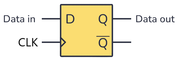 A diagram of the basic functions of the flip-flop electrical component. D is the input, Q is the output. Ignore the Q with the line for now ([[[). Courtesy of buildcircuitelectronics.
And here is a diagram showing how the output relies on clock signals to accept an input change, if any:
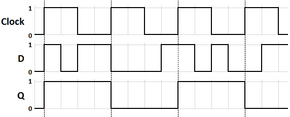 A diagram detailing how the clock signal will influence what data from the input is stored and produced in the output. As shown, the flip-flop will only store the first event captured in the input when the clock signal becomes active, regardless of whether the input changes while the clock signal is still active. Courtesy of Wikipedia.
The general symbology used in diagrams for a flip-flop (in which D is the input & Q is the output) is as follows:
And here is a diagram showing how the output relies on clock signals to accept an input change, if any:
#
C. Rule .
Shift Registers:
A "shift register" is a concatentation of several individual flip-flops. Each flip-flop has a starting bit-value, which it then uses to send a signal to each following flip-flop until the final one, which will produce each bit of the output. The combined bits taken from the final flip-flop form a keystream, as depicted in the diagram below. The shift register is one half of an LFSR (see Rule 32).
Very important to notice in the progress of the bits of a shift register towards the output, is that there is a distinct pattern that holds for each bit-value (placed below the flip-flops on the diagram), known as the Diagonal Rule: each bit-value will be translated diagonally rightward and downward, for as many flip-flops as there are to the right. Note this pattern in the diagram below:
An example of a shift register, with three flip-flops, with every new value sent receiving a clock signal:
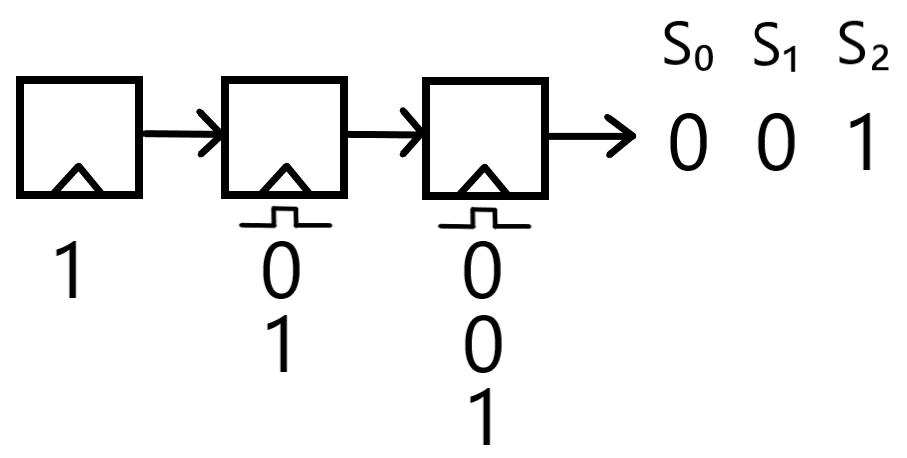 A shift register, complete with three flip-flops, and a starting value of 1-0-0. Data moves rightward as the result of a clock signal allowing each flip-flop to take in the data of the flip-flop to its left, and the Diagonal rule becomes visible in how the data values effectively move diagonally to the right from their initial position.
A "shift register" is a concatentation of several individual flip-flops. Each flip-flop has a starting bit-value, which it then uses to send a signal to each following flip-flop until the final one, which will produce each bit of the output. The combined bits taken from the final flip-flop form a keystream, as depicted in the diagram below. The shift register is one half of an LFSR (see Rule 32).
Very important to notice in the progress of the bits of a shift register towards the output, is that there is a distinct pattern that holds for each bit-value (placed below the flip-flops on the diagram), known as the Diagonal Rule: each bit-value will be translated diagonally rightward and downward, for as many flip-flops as there are to the right. Note this pattern in the diagram below:
An example of a shift register, with three flip-flops, with every new value sent receiving a clock signal:
III.IV Linear Feedback Shift Registers.
There is an inherent relationship between electrical engineering and Cryptography, specifically in how Cryptography developed: in the early days of the development of the Stream Cipher, the goal was to create a 'small' stream cipher, e.g. a stream cipher that could be implemented in hardware without using too much power.
Today, all stream ciphers fit one of two categories: ciphers optimized for software implementation, and ciphers optimized for hardware implementation. A prime example of the latter are "Shift Register-Based Stream Ciphers", in particular shift registers (see Rule 31) with a feedback mechanism, better known as Linear Feedback Shift Registers.
#
C. Rule .
Linear Feedback Shift Registers:
Mathematical Definition:
The equation depends on the specific characteristics of the LFSR. Specifically, the number of flip-flops, the number of mod 2 functions, and which flip-flops have mod 2 functions. The following formula applies to all LFSRs and is fully explained/derived in the LFSR Generalization (see Rule 33):
(Si, Pj) ∈ ℤ2
(i, j) ∈ ℤm
$$S_{m+i} \equiv \left( \sum_{j=0}^{m-1} S_{i+j} \times P_{j} \right) \mod 2$$
m = The number of flip-flops in the LFSR. This number determines both the length of the state register and the period (see Rule 34) of the output sequence.
i = The offset in the shift register, i.e., the number bit of the keystream that is being found. This is why it is ∈ ℤm - it can go no greater than m-1.
Sm + i = The bit inputted into the first flip-flop at the offset i, and outputted into the keystream at the offset m+i. That's the diagonal rule for you.
j = The index variable for each individual flip-flop, each of which has the potential to contribute to the feedback path, as determined by the feedback coefficient.
Si + j = The bit held by a particular flip-flop j at a specific offset i in the shift register. This is the value being inputted into the multiplier function from the flip-flop.
Pj = The feedback coefficient of the multiplier associated with flip-flop j. Either 0 or 1.
mod 2 = The modulus/remainder operator with respect to 2. Numbers can only be 0 or 1 in this reality - see Rule 24 for a full treatise.
Explanation:
Occasionally referred to as cryptographic "linear recurrences" by various demented individuals, Linear Feedback Shift Registers are yet another PRNG-based keystream generator, and are thus crackable with some effort (see Rule 39).
However, unlike other PRNGS like Linear Congruential Generators (see Rule 28) which have no function in real cryptography due to their absurd unsecurity, the LFSR finds application in many ciphers due to its usefulness as a primitive. These ciphers use multiple LFSRs to achieve greater security: the A51 cipher (see Rule [[[), for example, consists of 3. This greatly enhances the security of the cipher and validates the usage of LFSRs for legitimate cryptographic purposes (see Rule [[[).
LFSRs incorporate a standard Shift Register (as detailed in Rule 31) alongside a feedback mechanism/path, generating fresh input for the first flip-flop using some output data. The feedback path extends from the output of the rightmost flip-flop (which, as known from the shift register analysis in Rule 31, is the flip-flop whose bits form the keystream) and inputs into the first flip-flop.
Placed along the feedback path are modular 2 addition functions (a.k.a. XOR gates, detailed in Rule 24), which are performed between the bit from the final flip-flop (by virtue of it being the beginning of the feedback path) and atleast one other in the shift register. Multiple XOR-gates can be added along the feedback path to create additional mod 2 operations (inherently meaning mod 2 operations involving the product of another mod 2 operation from earlier along the feedback path), complicating the structure of the LFSR and enraging Oscar.
The mod 2 calculation is first performed in the initial state of the shift register (the "initialization vector" of the shift register - see the "State" definition), before the first clock cycle, pre-computing the value that will be used as input for the first flip-flop on the first clock cycle. Every clock cycle adds another row of bits below the flip-flops, accounting for the clock signals sent to each flip-flop and their subsequent outputs.
Once the bit travels all the way through the feedback path, having been XOR'd 1+ times with the bits from various points in the register, it is simply fed into the first flip-flop so that the shift register can have a new input value. The value of the bit inputted into the first flip-flop is the result of the summation of all of the possible XOR operations that could be present in the LFSR.
Since Shift Registers are an integral component of LFSRs, the Diagonal Rule previously described for Shift Registers (see Rule 31) is retained for the movement of bits within an LFSR, as shown in the diagram below:
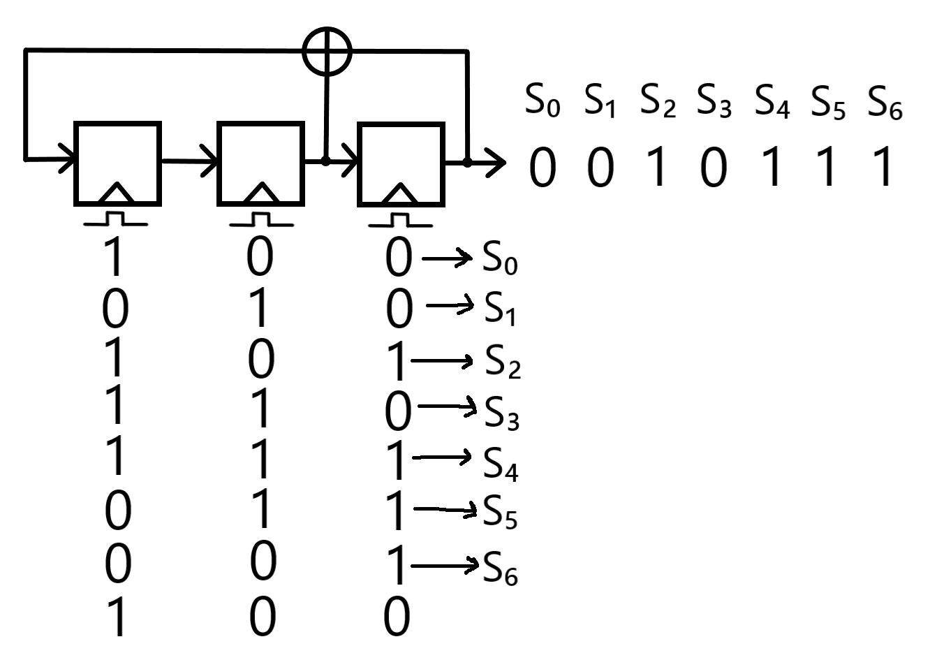 A Linear Feedback Shift Register, complete with three flip-flops and a full period of values, which compose one complete keystream.
The specific mathematical formula of the keystream produced by the depicted LFSR is (as a result of the diagonal rule): Si+3 ≡ (si+1 + si) mod 2.
Mathematical Definition:
The equation depends on the specific characteristics of the LFSR. Specifically, the number of flip-flops, the number of mod 2 functions, and which flip-flops have mod 2 functions. The following formula applies to all LFSRs and is fully explained/derived in the LFSR Generalization (see Rule 33):
(Si, Pj) ∈ ℤ2
(i, j) ∈ ℤm
$$S_{m+i} \equiv \left( \sum_{j=0}^{m-1} S_{i+j} \times P_{j} \right) \mod 2$$
m = The number of flip-flops in the LFSR. This number determines both the length of the state register and the period (see Rule 34) of the output sequence.
i = The offset in the shift register, i.e., the number bit of the keystream that is being found. This is why it is ∈ ℤm - it can go no greater than m-1.
Sm + i = The bit inputted into the first flip-flop at the offset i, and outputted into the keystream at the offset m+i. That's the diagonal rule for you.
j = The index variable for each individual flip-flop, each of which has the potential to contribute to the feedback path, as determined by the feedback coefficient.
Si + j = The bit held by a particular flip-flop j at a specific offset i in the shift register. This is the value being inputted into the multiplier function from the flip-flop.
Pj = The feedback coefficient of the multiplier associated with flip-flop j. Either 0 or 1.
mod 2 = The modulus/remainder operator with respect to 2. Numbers can only be 0 or 1 in this reality - see Rule 24 for a full treatise.
Explanation:
Occasionally referred to as cryptographic "linear recurrences" by various demented individuals, Linear Feedback Shift Registers are yet another PRNG-based keystream generator, and are thus crackable with some effort (see Rule 39).
However, unlike other PRNGS like Linear Congruential Generators (see Rule 28) which have no function in real cryptography due to their absurd unsecurity, the LFSR finds application in many ciphers due to its usefulness as a primitive. These ciphers use multiple LFSRs to achieve greater security: the A51 cipher (see Rule [[[), for example, consists of 3. This greatly enhances the security of the cipher and validates the usage of LFSRs for legitimate cryptographic purposes (see Rule [[[).
LFSRs incorporate a standard Shift Register (as detailed in Rule 31) alongside a feedback mechanism/path, generating fresh input for the first flip-flop using some output data. The feedback path extends from the output of the rightmost flip-flop (which, as known from the shift register analysis in Rule 31, is the flip-flop whose bits form the keystream) and inputs into the first flip-flop.
Placed along the feedback path are modular 2 addition functions (a.k.a. XOR gates, detailed in Rule 24), which are performed between the bit from the final flip-flop (by virtue of it being the beginning of the feedback path) and atleast one other in the shift register. Multiple XOR-gates can be added along the feedback path to create additional mod 2 operations (inherently meaning mod 2 operations involving the product of another mod 2 operation from earlier along the feedback path), complicating the structure of the LFSR and enraging Oscar.
The mod 2 calculation is first performed in the initial state of the shift register (the "initialization vector" of the shift register - see the "State" definition), before the first clock cycle, pre-computing the value that will be used as input for the first flip-flop on the first clock cycle. Every clock cycle adds another row of bits below the flip-flops, accounting for the clock signals sent to each flip-flop and their subsequent outputs.
Once the bit travels all the way through the feedback path, having been XOR'd 1+ times with the bits from various points in the register, it is simply fed into the first flip-flop so that the shift register can have a new input value. The value of the bit inputted into the first flip-flop is the result of the summation of all of the possible XOR operations that could be present in the LFSR.
Since Shift Registers are an integral component of LFSRs, the Diagonal Rule previously described for Shift Registers (see Rule 31) is retained for the movement of bits within an LFSR, as shown in the diagram below:
The specific mathematical formula of the keystream produced by the depicted LFSR is (as a result of the diagonal rule): Si+3 ≡ (si+1 + si) mod 2.
# Feedback Path/Feedback Mechanism: The path that allows for bits to be inputted back into the Linear Feedback Shift Register using output data, forming the "Linear Feedback" part of the LFSR. The path extends from the output of the rightmost flip-flop and inputs into the first flip-flop.
Placed along the feedback path are modular 2 addition functions (a.k.a. XOR gates, detailed in Rule 24), which are performed between the bit from the final flip-flop (by virtue of it being the beginning of the feedback path) and atleast one other in the shift register.
# State/Offset (in regard to LFSRs): The bits of the flip-flops at a particular row-position in the shift register. Given knowledge of an LFSR state and the XOR-positions/feedback path, every following row of bits can be determined.
The first state of an LFSR is known as the Initialization Vector.
Even without knowledge of the XOR positions, by pure knowledge of the first state, almost every flip-flop bit in the following state (except for the first F.F., the recipient of the input of the feedback state) can be determined, as a result of the diagonal rule of Shift Registers (see Rule 31).
# Taps/Tap Sequences: Know that there are alternate terminologies used in more pretentious and snobbish cryptographic circles. In these contexts, each outputted bit is referred to as a tap, while the full list of taps is known as the tap sequence. In the Summary of Cryptography, for the sake of simplicity, these terms will only be referred to as the "output bits" and "keystream", respectively.
#
C. Rule .
LFSR Generalization:
To construct a generalized LFSR so that a general equation can be applied, several new mathematical operations must be introduced.
First, the number of flip-flops in the register can be generalized to an arbitrary 'm' value.
The second generalization is a bit more complex: Understand that it is possible for any flip-flop in an LFSR to have its bits fed into an XOR gate on the feedback path, and for there to be as many XOR gates as flip-flops (minus one, since the rightmost flip-flops share one). Since every flip-flop can have an XOR gate (and thus be apart of the feedback path), a multiplier function (labeled P0 to Pm-1) is added along each flip-flop's tentative connection to the feedback path, serving as an intermediary between the flip-flop and any possible XOR gate above on the feedback path. The multiplier essentially acts as an on-or-off switch, activating depending on whether there actually is an XOR gate for that particular flip-flop or not, as detailed below.
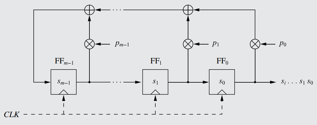 A generalized LFSR, with every possible link between a flip-flop and the feedback path having a multiplier function, serving as the 'switch' determining whether that flip-flop is included as a part of the XOR operation.
The multiplier function works by multiplying the value of the flip-flop by an internal P-value, known as the "feedback coefficient". The feedback coefficient, referred to as pi, is a value within the multiplier that only has two possible values: 1 if there is a XOR gate, and 0 if there isn't. Mathematically, this means that the feedback coefficient can only be a binary value: pi ∈ ℤ2.
The feedback coefficient is determined by whether the flip-flop actually has an XOR gate connected to it or not. For example, in the given diagram, every flip-flop has a corresponding XOR gate connected to it just above the multiplier, while in the diagram of Rule 32, only the middle flip-flop has an XOR gate.
Mathematically, the principal effect of the feedback coefficient lies in how it decides what value is outputted by the multiplier towards the feedback path. Specifically, the feedback coefficient (pi) is the determining factor in the multiplier equation: O = pi × I.
'I' refers to the bit inputted into the multiplier by the flip-flop (i.e., its bit-value at that particular clock cycle), and 'O' represents the output of the multiplier into the feedback path. As evident (and as detailed below), whether pi is 0 or 1 is the determining factor in whether the input is the same as the output.
If there IS an XOR gate for that flip-flop, and thus a connection to the feedback path, then the feedback coefficient will equal 1, since the input is equal to the output: O = pi × I = I.
If there's NO XOR gate, then the feedback coefficient will equal 0, since the output O must be equal to 0 in order for the inputted bit to have no impact on the feedback path. The output O is equal to 0, and since O = pi × I, and as I is not necessarily 0, then pi must equal 0.
In this way, the multiplier is like a border checkpoint, and the feedback coefficient is the inspector. If the XOR gate exists for the flip-flop that multiplier is serving, then the bit is granted unimpeded passage into the gate by the feedback coefficient. However, if no XOR gate exists, then the bit is effectively turned away; by altering the bit to 0, it is made irrelevant to the feedback path, since an addition of zero (the additive neutral element as detailed in the "Rules of the Ring" of Subsection II.III) contributes nothing to the end-result bit of the feedback path (that which is inputted into the leftmost flip-flop).
For the following formula, you must know two things about Sm: It is the sum of all of the XOR operations performed before the first clock cycle, i.e. the preloaded bit-value that is ready to be inputted into the first flip-flop after the initialization vector, and it doubles as the first outbit bit into the keystream that can be computed using the LFSR equation. Every S value before Sm is part of the initalization vector (as a result of the diagonal rule), which, of course, is composed of non-deterministic seed values which cannot be calculated.
Thus, after the first clock cycle, the second sum of every XOR operation performed along the feedback path (which, of course, involves a different set of bits (as a result of the second state) and produces the second bit-value inputted into the first flip-flop) will be Sm+1, and so on. This formula synthesizes every generalization made throughout the course of this Rule into a cohesive and elegant little package:
Mathematical Definition:
(Si, Pj) ∈ ℤ2
(i, j) ∈ ℤm
$$S_{m+i} \equiv \left( \sum_{j=0}^{m-1} S_{i+j} \times P_{j} \right) \mod 2$$
m = The number of flip-flops in the LFSR. This number determines both the length of the state register and the period (see Rule 34) of the output sequence.
i = The offset in the shift register, i.e., the number bit of the keystream that is being found. This is why it is ∈ ℤm - it can go no greater than m-1.
Sm + i = The bit inputted into the first flip-flop at the offset i, and outputted into the keystream at the offset m+i. That's the diagonal rule for you.
j = The index variable for each individual flip-flop, each of which has the potential to contribute to the feedback path, as determined by the feedback coefficient.
Si + j = The bit held by a particular flip-flop j at a specific offset i in the shift register. This is the value being inputted into the multiplier function from the flip-flop.
Pj = The feedback coefficient of the multiplier associated with flip-flop j. Either 0 or 1.
mod 2 = The modulus/remainder operator with respect to 2. Numbers can only be 0 or 1 in this reality - see Rule 24 for a full treatise.
To construct a generalized LFSR so that a general equation can be applied, several new mathematical operations must be introduced.
First, the number of flip-flops in the register can be generalized to an arbitrary 'm' value.
The second generalization is a bit more complex: Understand that it is possible for any flip-flop in an LFSR to have its bits fed into an XOR gate on the feedback path, and for there to be as many XOR gates as flip-flops (minus one, since the rightmost flip-flops share one). Since every flip-flop can have an XOR gate (and thus be apart of the feedback path), a multiplier function (labeled P0 to Pm-1) is added along each flip-flop's tentative connection to the feedback path, serving as an intermediary between the flip-flop and any possible XOR gate above on the feedback path. The multiplier essentially acts as an on-or-off switch, activating depending on whether there actually is an XOR gate for that particular flip-flop or not, as detailed below.
The multiplier function works by multiplying the value of the flip-flop by an internal P-value, known as the "feedback coefficient". The feedback coefficient, referred to as pi, is a value within the multiplier that only has two possible values: 1 if there is a XOR gate, and 0 if there isn't. Mathematically, this means that the feedback coefficient can only be a binary value: pi ∈ ℤ2.
The feedback coefficient is determined by whether the flip-flop actually has an XOR gate connected to it or not. For example, in the given diagram, every flip-flop has a corresponding XOR gate connected to it just above the multiplier, while in the diagram of Rule 32, only the middle flip-flop has an XOR gate.
Mathematically, the principal effect of the feedback coefficient lies in how it decides what value is outputted by the multiplier towards the feedback path. Specifically, the feedback coefficient (pi) is the determining factor in the multiplier equation: O = pi × I.
'I' refers to the bit inputted into the multiplier by the flip-flop (i.e., its bit-value at that particular clock cycle), and 'O' represents the output of the multiplier into the feedback path. As evident (and as detailed below), whether pi is 0 or 1 is the determining factor in whether the input is the same as the output.
If there IS an XOR gate for that flip-flop, and thus a connection to the feedback path, then the feedback coefficient will equal 1, since the input is equal to the output: O = pi × I = I.
If there's NO XOR gate, then the feedback coefficient will equal 0, since the output O must be equal to 0 in order for the inputted bit to have no impact on the feedback path. The output O is equal to 0, and since O = pi × I, and as I is not necessarily 0, then pi must equal 0.
In this way, the multiplier is like a border checkpoint, and the feedback coefficient is the inspector. If the XOR gate exists for the flip-flop that multiplier is serving, then the bit is granted unimpeded passage into the gate by the feedback coefficient. However, if no XOR gate exists, then the bit is effectively turned away; by altering the bit to 0, it is made irrelevant to the feedback path, since an addition of zero (the additive neutral element as detailed in the "Rules of the Ring" of Subsection II.III) contributes nothing to the end-result bit of the feedback path (that which is inputted into the leftmost flip-flop).
For the following formula, you must know two things about Sm: It is the sum of all of the XOR operations performed before the first clock cycle, i.e. the preloaded bit-value that is ready to be inputted into the first flip-flop after the initialization vector, and it doubles as the first outbit bit into the keystream that can be computed using the LFSR equation. Every S value before Sm is part of the initalization vector (as a result of the diagonal rule), which, of course, is composed of non-deterministic seed values which cannot be calculated.
Thus, after the first clock cycle, the second sum of every XOR operation performed along the feedback path (which, of course, involves a different set of bits (as a result of the second state) and produces the second bit-value inputted into the first flip-flop) will be Sm+1, and so on. This formula synthesizes every generalization made throughout the course of this Rule into a cohesive and elegant little package:
Mathematical Definition:
(Si, Pj) ∈ ℤ2
(i, j) ∈ ℤm
$$S_{m+i} \equiv \left( \sum_{j=0}^{m-1} S_{i+j} \times P_{j} \right) \mod 2$$
m = The number of flip-flops in the LFSR. This number determines both the length of the state register and the period (see Rule 34) of the output sequence.
i = The offset in the shift register, i.e., the number bit of the keystream that is being found. This is why it is ∈ ℤm - it can go no greater than m-1.
Sm + i = The bit inputted into the first flip-flop at the offset i, and outputted into the keystream at the offset m+i. That's the diagonal rule for you.
j = The index variable for each individual flip-flop, each of which has the potential to contribute to the feedback path, as determined by the feedback coefficient.
Si + j = The bit held by a particular flip-flop j at a specific offset i in the shift register. This is the value being inputted into the multiplier function from the flip-flop.
Pj = The feedback coefficient of the multiplier associated with flip-flop j. Either 0 or 1.
mod 2 = The modulus/remainder operator with respect to 2. Numbers can only be 0 or 1 in this reality - see Rule 24 for a full treatise.
#
C. Rule .
The Period is the length of the longest string of numbers before repeating in the keystream generated by an LFSR. It is thus also the number of possible offsets a LFSR can have before repeating a single one. For example, in a particular LFSR with 3 flip-flops (specifically the one given in Rule 32), the keystream is as follows:
001011100101110010111001011100101...
As seen, the keystream is just a string of "0010111" that repeats infinitely, meaning that the LFSR has a period of 7.
A simple principle can thus be derived: The maximum possible period (or sequence length) generated by an LFSR of degree m is 2m - 1.
As soon as a previous bit pattern/sequence (a 'state') is reached, the cycle will repeat itself, forming a 'state loop'. Only certain feedback configurations (Pm-1, ..., P0) yield maximum length periods, which will be maximum regardless of the initialization vector (!). For any non-maximum-period LFSR however, the initalization vector will affect how long the period is, as different initial states will result in state loops of different lengths.
For an example, consider a LFSR with five flip-flops and a non-maximum feedback configuration. With one initialization vector, the LFSR could have its states repeat after only three distinct rows, and for another initialization vector, could have its states repeat after ten distinct rows, all the while having the same feedback configuration. Different initialization vectors produce different state loops when the LFSR does not have a maximum-length feedback configuration.
This is why the given value is the maximum possible period of an LFSR - only some reach it. Furthermore, the reason for the "- 1" in the equation is because the maximum period incorporates all possible offsets except for one: 000. As detailed in Rule 35, it is impossible for an all-zeroes row to appear in an LFSR, and thus the highest period an LFSR can strive for is 2m - 1.
There are patterns within the LFSR, specifically that of the positioning of the XOR gates with respect to the degree m, that can be used to determine if an LFSR will produce a maximum-length period or not - see Rule 38 for more information. These patterns require knowledge of the Polynomial Representation of LFSRs - see Rule 37.
#
C. Rule .
The only string of bits that can never appear in an LFSR state is straight 0's. Such a thing is only possible if the initial setting is all straight 0's, which is a ridiculous thought not to be entertained.
# Primitive Polynomials: A special type of irreducible polynomial. An irreducible polynomial is akin to a "prime" polynomial, with the only factors being 1 and the polynomial itself. While the application of primitive polynomials in Cryptography is fairly extensive (as seen in Rule 36 & Rule 38), a more detailed analysis of them (and the exact difference between them and irreducible polynomials) can be found in Math Rule [[[.
#
C. Rule .
Types of LFSRs:
In practice, there are three types of LFSRs, the properties of which are the result of the feedback coefficients and degree.
In practice, there are three types of LFSRs, the properties of which are the result of the feedback coefficients and degree.
- Primitive Polynomial-based: These LFSRs are composed of primitive polynomials (see definition), and produce a maximum-length period, the only LFSRs to do so.
- Non-Primitive Irreducible Polynomial-based: Using irreducible polynomials that are not "primitive", these LFSRs produce a period that is totally independent of the initial value/"state" of the register. These algorithms do not produce maximum-length sequences.
- Reducible Polynomial-based: These LFSRs have a sequence/period dependent on the initial state of the register. Of course, these algorithms can never produce a maximum-length sequence.
#
C. Rule .
Polynomial Representation of LFSRs:
All that is needed to represent a LFSR mathematically (aside from the initialization vector) is the degree m (the number of flip-flops), and the feedback coefficients. These characteristics can be represented in polynomial form as so:
P(x) = xm + Pm-1 × xm-1 + ... + P1 × x + P0
m = The number of flip-flops.
x = The simple polynomial variable, nothing to be plugged in. The different variables are differentiated by their exponents in the equation.
Pm-1 = The feedback coefficient of the leftmost multiplier function in the register. The sequence Pm to P0 represents all multiplier functions, left to right. Because it multiplies the variable, if the feedback coefficient for a particular flip-flop is zero (no XOR gate), then that variable is nullified and removed from the polynomial. If the coefficient is one (XOR gate exists), then the variable remains. This is the intuitive genius of polynomial representation.
For example: The LFSR depicted in Rule 32 would be represented as x³ + x + 1.
Even if there weren't XOR gates in the entire LFSR, the equation would still be xm + 1, representing the ending and beginning points of feedback path.
Note that the number of variables in the polynomial does not represent the number of flip-flops - it represents the number of connections to the feedback path. For example, if there are 3 flip-flops in a register, then there are 4 possible connections, of which the leftmost and rightmost are guaranteed (as stated in the paragraph above). The other two connections are the ones with actual multiplier functions that decide whether they have an XOR gate, and thus whether they are a part of the polynomial. The variables absent from the polynomial give as much information as those included.
Depicted in the illustration below are the placements of the polynomial variables in relation to the feedback paths/connections they actually represent. Each middle flip-flop is incorporated into the feedback path (and thus into the polynomial) with its own XOR gate. Any minor confusion over the previous explanations should be resolved by the image below.
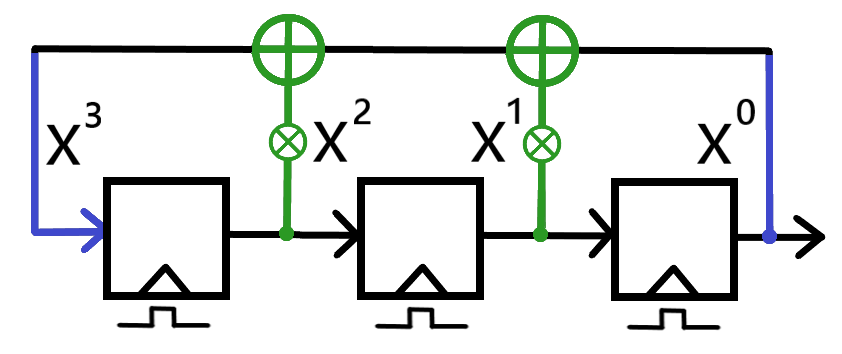 An illustration of how each variable of an LFSR polynomial accounts for the feedback path connections of an LFSR. The depicted LFSR has three flip-flops and both possible XOR gates, meaning that the polynomial has every variable present.
There are patterns in LFSR polynomials that can be used to determine whether the LFSR has a maximum-length period or not: see Rule 38.
All that is needed to represent a LFSR mathematically (aside from the initialization vector) is the degree m (the number of flip-flops), and the feedback coefficients. These characteristics can be represented in polynomial form as so:
P(x) = xm + Pm-1 × xm-1 + ... + P1 × x + P0
m = The number of flip-flops.
x = The simple polynomial variable, nothing to be plugged in. The different variables are differentiated by their exponents in the equation.
Pm-1 = The feedback coefficient of the leftmost multiplier function in the register. The sequence Pm to P0 represents all multiplier functions, left to right. Because it multiplies the variable, if the feedback coefficient for a particular flip-flop is zero (no XOR gate), then that variable is nullified and removed from the polynomial. If the coefficient is one (XOR gate exists), then the variable remains. This is the intuitive genius of polynomial representation.
For example: The LFSR depicted in Rule 32 would be represented as x³ + x + 1.
Even if there weren't XOR gates in the entire LFSR, the equation would still be xm + 1, representing the ending and beginning points of feedback path.
Note that the number of variables in the polynomial does not represent the number of flip-flops - it represents the number of connections to the feedback path. For example, if there are 3 flip-flops in a register, then there are 4 possible connections, of which the leftmost and rightmost are guaranteed (as stated in the paragraph above). The other two connections are the ones with actual multiplier functions that decide whether they have an XOR gate, and thus whether they are a part of the polynomial. The variables absent from the polynomial give as much information as those included.
Depicted in the illustration below are the placements of the polynomial variables in relation to the feedback paths/connections they actually represent. Each middle flip-flop is incorporated into the feedback path (and thus into the polynomial) with its own XOR gate. Any minor confusion over the previous explanations should be resolved by the image below.
There are patterns in LFSR polynomials that can be used to determine whether the LFSR has a maximum-length period or not: see Rule 38.
#
C. Rule .
Deriving Maximum-Length Periods from LFSR Polynomials:
Only LFSRs with primitive polynomials (see definition) yield maximum-length sequences.
Below is a table showcasing an example primitive polynomial for each m value 2-128. Note that there are multitudes of primitive polynomials for any given m value, too many to produce a complete list. There are 6.92 × 10⁷ primitive polynomials for an LFSR of m 31.
In the table below, take the values as representing the degrees in reverse order: x^0 + x^1 + x^2, for example. This ensures the +1, a necessary component of any LFSR polynomial as explained in Rule 37.
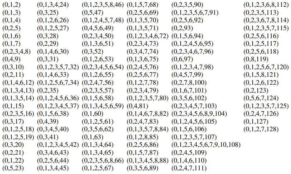 A table showcasing an example primitive polynomial for each m value 2-128.
Only LFSRs with primitive polynomials (see definition) yield maximum-length sequences.
Below is a table showcasing an example primitive polynomial for each m value 2-128. Note that there are multitudes of primitive polynomials for any given m value, too many to produce a complete list. There are 6.92 × 10⁷ primitive polynomials for an LFSR of m 31.
In the table below, take the values as representing the degrees in reverse order: x^0 + x^1 + x^2, for example. This ensures the +1, a necessary component of any LFSR polynomial as explained in Rule 37.
#
C. Rule .
HOW TO CRACK A LINEAR FEEDBACK SHIFT REGISTER (LFSR):
Linear Feedback Shift Register's have many attractive properties, such as relative randomness and extraordinary efficiency - 100 flip-flops, a miniscule amount of space in hardware, produces a period of 2¹⁰⁰ - 1, for example. However, it fails on the last hurdle towards cryptographically secure generation: unpredictability.
By its very nature, an LFSR is a PRNG, a deterministic means of producing a keystream, thus opening it up to many vulnerabilities that can be exploited. The main principle that must be acknowledged in attempting to 'break' or 'crack' any stream cipher that utilizes an LFSR is as follows:
If an attacker knows (at least) 2m output values of an LFSR, he can recover the entire LFSR configuration, and from there, the plaintext.
Oscar must have the following prerequisite knowledge in order to crack the LFSR: Oscar, as always, must know the complete ciphertext string. Furthermore, he must know the degree m of the LFSR, i.e. the number of flip-flops in the register. This is reasonable knowledge to assume in real life, since the specifications of most cryptographic algorithms (including the m value) are made freely available under Kerckhoffs' Principle (Rule 3). Most damningly, he must also know the first few plaintext characters: x0, ..., x2m - 1. Much in the same fashion as how the Linear Congruential Generator was cracked (see Rule 29), it can be assumed that the header information of the document supplies this plaintext, and thus it is still realistic for that amount of plaintext to be known to the attacker.
Given this knowledge, Oscar simply has to follow a 3-step process in order to recover the entire key:
i ∈ ℤ2m
Si ≡ (xi + yi) mod 2.
Since Oscar knows the first 2m bits of both the plaintext and ciphertext, he is able to recover the first 2m keystream bits of the LFSR, which is still not enough: the maximum possible period is 2m - 1, so there remain a considerable number of keystream bits that need to be recovered before a complete decryption of the plaintext is possible.
Sm ≡ (Sm-1 × Pm-1 + ... + S0 × P0) mod 2
Since Oscar conveniently knows the m value, the only unknowns in this equation are every single feedback coefficient. Thus, there are a total of m unknowns that need to be solved for. In order to solve for m unknowns, a system-of-equations type problem, with m equations, must be created:
Sm ≡ (Sm-1 × Pm-1 + ... + S0 × P0) mod 2
Sm+1 ≡ (Sm × Pm-1 + ... + S1 × P0) mod 2
.
.
.
S2m-1 ≡ (S2m-2 × Pm-1 + ... + Sm-1 × P0) mod 2
As was done for Linear Congruential Generators, each unknown can easily be solved for by Gaussian Elimination ([[[[[) or Matrix Inversion ([[[[[[[[).
He can determine the initial state using the output bits that are already known (using the Diagonal Rule, see Rule 31), and from there he will be able to compute the full keystream, S2m+1 and beyond.
With the keystream, Oscar will now, of course, be able to recover the full plaintext:
xi ≡ (yi + si) mod 2
Linear Feedback Shift Register's have many attractive properties, such as relative randomness and extraordinary efficiency - 100 flip-flops, a miniscule amount of space in hardware, produces a period of 2¹⁰⁰ - 1, for example. However, it fails on the last hurdle towards cryptographically secure generation: unpredictability.
By its very nature, an LFSR is a PRNG, a deterministic means of producing a keystream, thus opening it up to many vulnerabilities that can be exploited. The main principle that must be acknowledged in attempting to 'break' or 'crack' any stream cipher that utilizes an LFSR is as follows:
If an attacker knows (at least) 2m output values of an LFSR, he can recover the entire LFSR configuration, and from there, the plaintext.
Oscar must have the following prerequisite knowledge in order to crack the LFSR: Oscar, as always, must know the complete ciphertext string. Furthermore, he must know the degree m of the LFSR, i.e. the number of flip-flops in the register. This is reasonable knowledge to assume in real life, since the specifications of most cryptographic algorithms (including the m value) are made freely available under Kerckhoffs' Principle (Rule 3). Most damningly, he must also know the first few plaintext characters: x0, ..., x2m - 1. Much in the same fashion as how the Linear Congruential Generator was cracked (see Rule 29), it can be assumed that the header information of the document supplies this plaintext, and thus it is still realistic for that amount of plaintext to be known to the attacker.
Given this knowledge, Oscar simply has to follow a 3-step process in order to recover the entire key:
Step 1:
Utilizing the definition of the encryption function of a stream cipher (Rule 25), the keystream at position i can be isolated:i ∈ ℤ2m
Si ≡ (xi + yi) mod 2.
Since Oscar knows the first 2m bits of both the plaintext and ciphertext, he is able to recover the first 2m keystream bits of the LFSR, which is still not enough: the maximum possible period is 2m - 1, so there remain a considerable number of keystream bits that need to be recovered before a complete decryption of the plaintext is possible.
Step 2:
In order to discover the remaining bits, the feedback coefficients of the multiplier functions must be discovered. This is done using the generalized summation equation of the LFSR (Rule 33). Expanding out the summation will produce the following equation:Sm ≡ (Sm-1 × Pm-1 + ... + S0 × P0) mod 2
Since Oscar conveniently knows the m value, the only unknowns in this equation are every single feedback coefficient. Thus, there are a total of m unknowns that need to be solved for. In order to solve for m unknowns, a system-of-equations type problem, with m equations, must be created:
Sm ≡ (Sm-1 × Pm-1 + ... + S0 × P0) mod 2
Sm+1 ≡ (Sm × Pm-1 + ... + S1 × P0) mod 2
.
.
.
S2m-1 ≡ (S2m-2 × Pm-1 + ... + Sm-1 × P0) mod 2
As was done for Linear Congruential Generators, each unknown can easily be solved for by Gaussian Elimination ([[[[[) or Matrix Inversion ([[[[[[[[).
Step 3:
Now that Oscar knows all of the Feedback Coefficients, he can build the LFSR himself.He can determine the initial state using the output bits that are already known (using the Diagonal Rule, see Rule 31), and from there he will be able to compute the full keystream, S2m+1 and beyond.
With the keystream, Oscar will now, of course, be able to recover the full plaintext:
xi ≡ (yi + si) mod 2
III.V Alternate Secure Stream Ciphers.
During the 1990s, stream ciphers were a center of attention for many cryptanalysts, who ruthlessly revealed vulnerabilites and weaknesses that opened particular popular ciphers of the time - this would fuel the predominance of block ciphers in modern cryptographic communications.
As a result, the eSTREAM project was established in 2004 by the "European Network of Excellence in Cryptology" (an E.U. front), which called for the development (and expert selection) of stream ciphers.
By 2008, several new, highly secure stream ciphers were developed, divided into two main categories/profiles:
1. Stream ciphers designed for implementation in software with high-volume data transfer requirements. Examples: Salsa20 (see Rule 40) & ChaCha (see Rule [[[[).
2. Stream ciphers designed for hardware implementation, with low power consumption, storage capabilities, and gate counts. Example: Trivium (see Rule [[[[).
# Add-Rotate-XOR (ARX) Ciphers: An algorithm in a cryptosystem that only uses additions, rotations, and XOR operations to generate its keystream.
# "Nonce": A number used only once.
#
C. Rule .
Salsa20:
Mathematical Definition:
[[[[[To be completed at a later date. I have determined this topic: "Salsa20", to be non-essential to the learning and understanding of the major fundamentals of Cryptography, and so it has been placed in the low-priority learning register.[[[[[
Explanation:
"Salsa20" is a family of profile-1 stream ciphers, developed in 2005. The PRNG utilizes a 32-bit ARX framework, with additional layers of security added through increased 'rounds' of encryption: the base cipher (Salsa20/20) uses 20 ciphers, while reduced-round, faster varients use 12 rounds (Salsa20/12) and 8 rounds (Salsa20/8), respectively.
Salsa20/20 (hereafter referred to as "Salsa20") supports key-lengths of either 128 or 256 bits, though 256 is recommended.
[[[[[To be completed at a later date. I have determined this topic: "Salsa20", to be non-essential to the learning and understanding of the major fundamentals of Cryptography, and so it has been placed in the low-priority learning register.[[[[[
#
C. Rule .
[[[[[Reserved for Future Usage. If additional rules are needed, then the WoO system will be used.[[[[[
[[[[[To be completed at a later date. I have determined this topic: "Salsa20, ChaCha, and Trivium", to be non-essential to the learning and understanding of the major fundamentals of Cryptography, and so it has been placed in the low-priority learning register.[[[[[
[[[[[To be completed at a later date. I have determined this topic: "Salsa20, ChaCha, and Trivium", to be non-essential to the learning and understanding of the major fundamentals of Cryptography, and so it has been placed in the low-priority learning register.[[[[[

